Earthing is an important protocol that guarantees the human’s safety and protective equipment by preventing overvoltage from passing. Based on Kahramaa standards and the British standards, to design a reliable earthing system for the building and the substation devices, the total earthing resistivity for each earthing system should be less than 5 Ω.
Earthing System for Whole Building:
According to the British standards, which is the standards used in Qatar, the earthing resistivity for single rod depends on several parameters, as shown in equation 6-1:
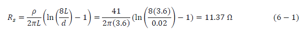
Where:
In Qatar, the soil type is sand which has a resistivity that varies from 20.54-61.25 Ω.m. Thus, the average value of the soil resistivity will be considered as 41 Ω.m. The length of the rod is 3.6 m as it is the most used in Qatar. Also, the size of the conductor should be 95 mm2 with a diameter equal to 0.02 m. By substituting these values in the equation, the earthing resistance will equal 11.37 Ω which is not acceptable.
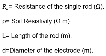
Since the single rod method did not lead to the required earthing resistance, the hollow square method will be applied to reduce the total earthing resistance. Equation 6-2 shows the calculation of the total earthing resistance using the hollow square:
As presented in equation 6-2, the total resistance depends on the resistance of a single rod and on the factor () that is decided in the British standards, which varies depending on the number of rods in each side of the hollow square ( n = N/4 + 1 ) that is required to be installed. However, for four rods it is equal to 2.71. According to the regulations, the spacing between the rods should be double the length of a single rod (7.2 m). The calculated total earthing resistance is equal to 3.46 Ω which is acceptable as it is less than 5 Ω. According to the Kahramaa standards, the earthing cable size that is used for the building is varying from 95mm2 to 120 mm2. A 120mm2 was selected as it is safer.
Earthing System for Transformer:
The earthing system will be designed for the transformer to protect the electrical equipment and the people walking around from any hazards, since the transformer supply high power to the building.
The transformer will have three earthing points, each point will have multiple rods parallel to each other to reduce the total earthing resistance to be less than 5 Ω, as per Kahramaa standards. One of the points will be supplied from Kahramaa and the other two will be calculated using the previous method utilized for the building’s earthing:
The single rod resistivity (equation 6-1):
![]()
Since R_s = 11.37 > 5 Ω , the multiple rods method will be used.
The total earthing resistivity (equation 6-2): ![]()
R_s = 3.46 < 5 Ω which is met with the standards.
Corresponding to Kahramaa, the fault current of the selected dry type transformer (1000kva) is equal to 44kA. By using this information, an online calculator was utilized to find the cable size [29] and it is found to be 560mm2. The earthing cross sectional area should be greater than 120mm2 for cable size that was obtained. Therefore, a 240mm2 was chosen as it is the available size in Qatar.
Earthing Cables for the SMDBs:
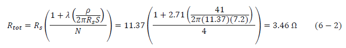
For each three-core cable of the SMDBs, an earthing core should be added to protect the building by avoiding any excessive electricity. As demonstrated in Table 6-1, the earthing core size was calculated based on the cable size.
Table 6‑1: Earthing Cable Sizes for SMDBs
![]()
![]()