Practical Testing of OBC
Software Testing:
In this section, a Simulink block was made; this block incorporates a unit step wave generator. This unit wave will enter an implicit block (PWM generator), which makes a pulse wave signal. Moreover, the frequency of the pulse wave is specified in the ePWM generator block. This wave is then being sent to the DSP to control the converters. It is pivotal before ordering the Simulink program to ensure availability between the Simulink program and the DSP, which implies the CCS is working and shows a legitimate network between the Simulink program and the DSP.
Practical Testing:
The practical system is implemented, as shown in Figure 4-3 below. All the results have been obtained from the test bench. The tested system is a scaled-down version OBC where the power is reduced from 4kW to 200W with an output voltage of 12 V. The whole system used is a boost followed by a buck DC-DC converter. The rectifier is used to convert the input signal from AC to DC while the transducer is used to receive analog values of voltage and current then transfer it to the DSP.
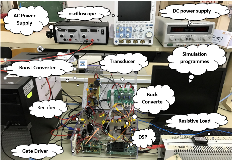
Figure 4‑5 OBC practical implementation.
The testing of the system involved checking the functionality of the rectifier and the boost converter that is operating in CCM mode. The two components were connected to check for the input current and the inductor current. The boost converter receives a specified duty cycle control signal from the gate driver to control the switching process of the MOSFET at a 0.5 duty cycle. The voltage received by the rectifier was an ac voltage (4.5 Vrms), and the input voltage and current were displayed in an oscilloscope, as shown below.
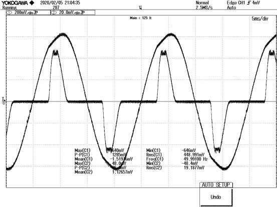
Figure 4‑6 The Input Voltage and Current Waveform of Open Loop.
Note that the waveform shown in Figure 4-4 is presenting the current and scaled-down voltage (1-10) of the AC input. Besides, the inductor current of the boost converter for the open-loop system is displayed below, showing that the converter is operating in the CCM.
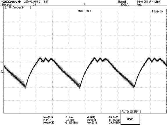
Figure 4‑7 The Inductor Current of the Boost.
The output voltage of the full-wave rectifier has been measured to ensure a minimum level of ripples. Figure 4-8 is shown the output voltage of the rectifier.
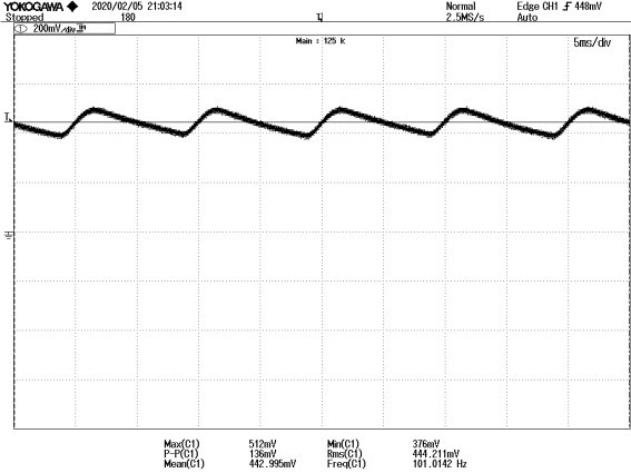
Figure 4‑8 Rectifier Output Voltage.
IoT Implementation,Testing Results and Components
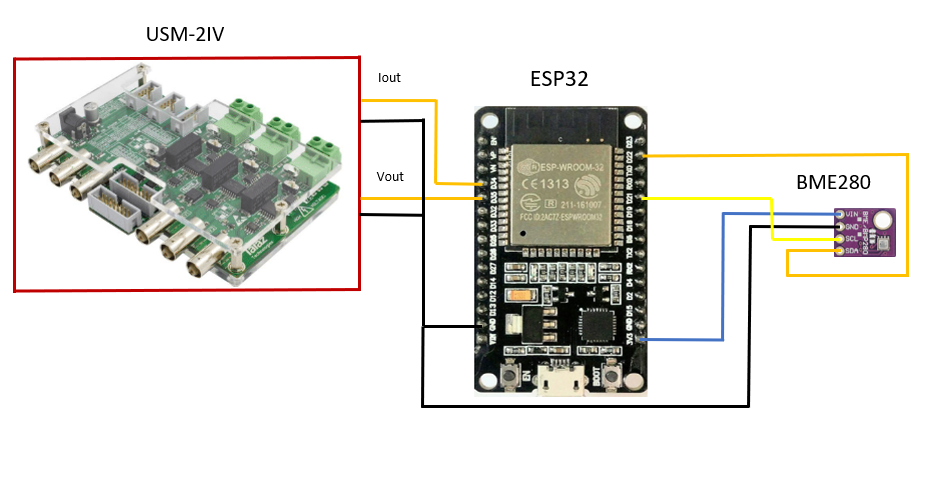
Figure 4‑3 IoT Platform.
One advantage of the esp32 is that it has a built-in library in which it can be installed within the Arduino software code. For instance, one library automatically checks for the connectivity between the bme/bmp280 sensor and the esp32 and also allows the user to retrieve the data from the bme/bmp280 through a one-line command. The voltage and current measurements retrieved from the USM-3IV are first changed from there decimal value to their actual value, then a scaling up by (x10) is implemented since the transducer scale down the voltage and current readings by (1/10). The software code also includes commands for sending the data to the application every 0.5 s through wifi.One thing to be noted is that the code needs to be downloaded only one time to the esp32. Then the esp32 can be connected to any home-like sockets through a phone-like adapter for providing the necessary power to operate. Blynk interference is shown in the figure below.
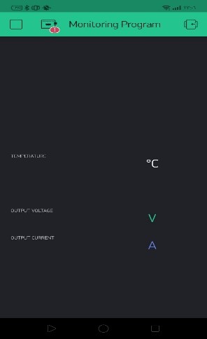
Figure 4‑4 Blynk Application for Real-Time Monitoring.
After programming and configuring all sensors with the (ESP32), the testing of the entire circuit is going to be conducted where all components must be powered by the esp32 while the esp32 chip must be power by any household socket. Below is the design of the circuit. And because of the coronavirus (COVID 19), the testing is done by measure the natural weather to test the sensors’ results.
BME/BMP280:
The purpose of using this sort of module is that contains three different sensors in a single module. the circuit will be basic as far as to install and configuration. furthermore, this module is that the readings of all sensors in this module are exact regarding the readings. Additionally, the cost of this module is cheaper than the other sensors. For instance, a good quality sensor like (DHT22) is costlier than BME/BMP280. Moreover, the module has only three different sensors with an extra elevation perusing while the (DHT22) has just two sensors [11]. however, there are some problems regarding using this sensor, the first problem is the BME/BMP280 has been tried finally and with the BME/BMP280 model is that it has two sections, one section for the pins and the subsequent part is containing the chip. To interface the two sections for all time, it requires welding them together.
IoT Mobile Application:
After building the user’s interface on the Blynk platform, it has been faced some limitations on the usage of the display indicators. For example, Blynk has a certain amount of (points=power) that allows the designer to work by this limit. Also, if the gauge indicator is used, there will be (300 points) will be deducted or if the bar is used, (500) points will be deducted from the total points (2500). This limitation can be avoided by buying more points from the stock of Blynk which is considered as a disadvantage.
On the other hand, the advantages of Blynk is that it simplifies the way where the designer used to put the pins and defining them in the code.
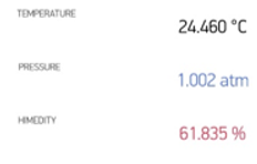
Figure 4‑12 Mobile Application Screen.