Power Loss Analysis
To evaluate the system performance, it is required to measure and calculate the systems’ efficiency. Many factors are affecting the efficiency which are the conduction losses and switching losses. Usually, conduction losses are the passive elements inside the electrical circuit like inductors and diodes. On the other hand, switching losses are related to transistors used in the circuit.
MOSFET Losses:
In general, Silicon Carbide Power MOSFET (SiCis used to improve the efficiency of the system by its capability of working under higher frequencies with minimal loss. Besides, external factors will influence the number of losses and heat generated by MOSFET. Heat sinkers have used in the circuit to minimize the heat and enhance efficiency.
There are three types of losses related to transistors which are switching, conduction, and blocking (leakage) losses. The difference between both types is that the switching losses are related to the energy which causes to turn on and off the switch -transistor – frequently. This will result in heating the transistor which will generate losses. The second kind of loss is about the internal structure (material) that is used to manufacture the transistor. The material used in (SiC) has a high ability ten conduct and can work within a harsh temperature range (-55 to 150 oC) see Appendix. Moreover, due to good conduction capability, conduction losses will occur. The blocking (leakage) losses are normally neglected.
To find the switching losses, the switching energy for the cases of on and off are needed to be calculated. Equation 4.1 and 4.2 are showing the energy for on and off switching conditions respectively.
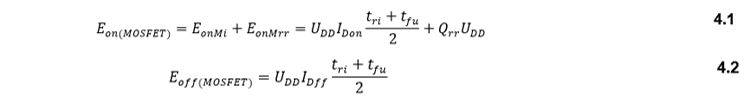
Where (EonMi) is the energy with considering reverse recovery condition and (EonMrr) is the energy caused by revers recover of fly wheel diode. (Udd and Idon) are energy of fly wheel diode and the current when the diode is on respectively. (Qrr) is the reverse recovery charge and (tri,tfu) the rise and fall time of the voltage at the gate respectively. Equation 4.1 and 4.2 above, the switching losses of the MOSFET is obtained by equation 4.3 below.

Where (Eon, Eoff) from the appendix (MOSFET SiC) datasheet and (Fsw) is the switching frequency. On the other hand, the conduction losses of the MOSFET can be calculated from equation 4.4 as shown below.

Where (Ron) is the internal resistance of the MOSFET and (Irms) is the RMS current of the MOSFET. To find the RMS current, equation 4.5 is used as shown below.

Where (Idc) is the average current and (Im) is the difference between the average and the peak.
Diode Losses:
Diodes are having losses that are related to conduction losses. The type of diodes that are used is Silicon Carbide Schottky Diode (SiC). This type of diode is used where the forward voltage drop is less and about (0.4 V) to enhance the efficiency of the circuit. Equation 4.6 is used to calculate the conduction losses of diodes.
![]()
Where (Von, I) is the forward voltage and forward current of the diode respectively.
Analysis of Power Loss
The system is consisting of the full-bridge rectifier and isolated SEPIC converter. Moreover, it has five Schottky diodes and one MOSFET (SiC) transistor. Since the switching losses are neglected because of the ideal switching assumption. It cannot be ignored for practical cases. Note that, the high switching frequency will increase switching losses. The switching frequency of the system which is 30kHz. By substitution all the value in equation 4.3 above.
![]()
Conduction losses are related to diodes, inductors, and transistors used in the circuit. The inductor losses are assumed to be minimal while diodes and transistors are having losses. The forward voltage of SiC Schottky diode is (0.8 V) and the forward current will be different based on the diode location in the circuit. Since the OBC circuit has two different locations of diodes, two different calculations have done separately and it is calculated by equations 4.8 and 4.9 respectively.

For the transistor, MOSFET conduction losses can be calculated using equation 4.4 above. Besides, the RMS value of the current is calculated by equation 4.5 above. Equations 4.10 and 4.11 are showing the calculations of RMS current and the conduction losses of the MOSFET.

Note that the power dissipation (125 W) for the MOSFET and (108 W) for diodes as shown in the appendixes (SiC) MOSFET and (SiC) Schottky Diode datasheet. Thus, the MOSFET conduction losses will be considered as (125 W).
The power efficiency of the system has calculated under full load conditions. Moreover, the power efficiency is calculated by equation 4.12.

The power efficiency at full load will be:

To illustrate the power efficiency, figure 4-13 has plotted from no load to full load condition.
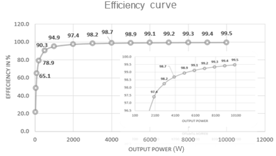
Figure 4‑13 Efficiency curve.