- Leakage inductor selection.
To get the appropriate leakage inductance value for this design the following equation is used, this equation is derived by the power on the transformer
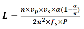
L: leakage inductance.
Vp: Primary voltage.
Vs: Secondary voltage.
![]() : phase shift angle between primary voltage and secondary voltage.
: phase shift angle between primary voltage and secondary voltage.
Fs: switching frequency.
P: Power.
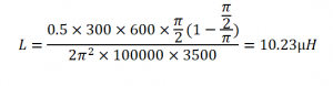
And by substituting in this formula with the design parameters the leakage inductance value is
- Phase shift angle selection.
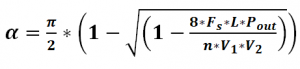
As discussed in the following equation the phase shift between the square waves for both bridges controls the direction and amount of power flow depending on the phase shift angle.
![]()
: Phase shift angle between primary voltage and secondary voltage.
Fs: Switching frequency.
Z: Leakage inductance.
Pout: Required output power.
n: Transformer ratio.
Vp: Voltage at primary side.
Vs: Voltage at secondary side.
To calculate the needed phase shift for the required power (3.4) is used and angles for maximum power in both directions meaning positive and negative values and those angles are the borders and any angle in between those borders results in a different power but the values of power never exceed the maximum power. Furthermore, by substituting the parameters in (3.4) the phase shift angle borders are deduced.
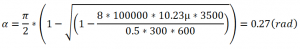
And the angle for the negative full power is the same but in negative. So, the phase shift angle values are:
![]()