Software and Hardware Used
After the simulation was fully implemented, the practical implementation is going to be started. The system is an on-board high-power battery charger for low-speed electric vehicles, for instance, golf cars. It contains a full bridge rectifier to convert the single-phase () AC input to a DC voltage, which is entering a SEPIC converter closed loop with two PI controllers and at the end the output of the charger. The values used are scaled down from the values in the simulation for safety purposes. In addition to the hardware connection, there will be a programmable software design and other components which relate the hardware part and the software part, which will be explained further below.
Software Programs:
MATLAB/Simulink and Code Composer Studio:
MATLAB/Simulink is the program used for the simulation of the control part that is responsible for the main hardware part to function in the desired way. This program provides some tools that can implement mathematical computation, tools that represent electrical equipment, and other tools that allow interfacing with DSP units and other electrical units. Simulink can be used for simulating the original design in such a way that it minimizes the time and effort needed for testing the design, In this project, Simulink is going to be used control to control the converters and receive data from the DSP in a closed-loop fashion.
Code Composer Studio (CCS): This software is used with the Digital Signal Processors (DSPs) to provide a communicating platform between the MATLAB/Simulink and (DSP) to simplify the communication between the MATLAB/Simulink model and DSP. Also, it supports TI embedded processors and microcontrollers [10].
Hardware:
Transducer Board:
This board is essential in the closed-loop control design. It includes ports that sense voltages and currents and steps down the voltage in a 1-10 ratio or 1-100 ratio. This equipment is used to minimize the power of the electric signal measured so that it can be exported to the (DSP), The Transducer board, in this case, is USM-3IV This transducer contains USM series of measurement modules that are with high performance, completely isolated, and have a multichannel voltage and current sensing modules [11].
The Gate Driver Circuit:
The gate driver circuit is used in power electronics applications where the circuit is controlled by a PID controller where the received signal’s power is small. The role of the gate diver circuit is to amplify the power and signal magnitude. Also, it is working as a buffer between the DC/DC converters and (DSP). During this project, two gate driver circuits have been used where one is connected to the buck converter, and the other is connected to the boost converter. Both the gate drives receive the controlled signal from the DSP and are powered by a 5 V DC supply.
Digital Signal Processor (DSP):
The digital signal processor (DSP) is the control unit for digital signals. This unit can operate 150 M floating-point operation/second, a RAM that is used for storing the data, and a USP port to receive data from the Simulink. This DSP is used to receive the data from the transducer board regarding voltage and current readings through an ADC, to send the information to the Simulink program. The DSP is also used to apply the control signal with the specified duty cycle to control the converters. The DSP unit used is (ezdsp TMS320F28335).
Practical Design for Intelligent Part
Intelligent OBC:
In this part, a brief description of an intelligent system is going to be explained. First, this system is simply a monitoring system in which it can detect any abnormality in either the OBC or the battery connected to the output of the OBC. This system then will contact the user of the EV to provide them with the necessary information needed for the monitoring proposes. So far, the needed information for the monitoring are the temperature, and the OBC output voltage and current.
Components Needed:
Now, for creating this monitoring system, few things need to be available. First is an electronic chip that includes a microcontroller, processor, and a memory that can receive data from the physical world and perhaps applying commands in other cases. The chip used was DOIT ESP32 DEVKIT V1 PINOUT , this chip can be used to read data from the OBC and the batteries needed for monitoring.
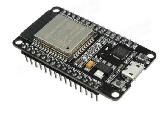
Figure 4‑1 ESP32 DEVKIT V1.
The second component is the temperature sensor. since the temperature can show if there is any burned component such as capacitors. Additionally, if there is any short circuit inside the OBC, the resulting high currents are going to raise the temperature of the circuit parts affected by the short circuit, which can be detected by a temperature sensor. In this case, bme/bmp280 can be used to measure the temperature. This sensor can provide multiple readings with a range of reading that is sufficient for our use. The temperature reading only is going to be of interest as the sensor can sense temperature ranging from -40 to 85 oC. This sensor has four peripherals, in which they are connected to the ESP32.
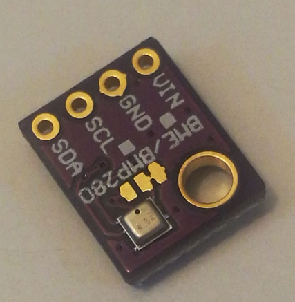
Figure 4‑2 bme/bmp280.
The third components are the application. This application needs to automatically connect to the esp32 while continually receiving data from the esp32, as well as displaying the temperature and voltage/current statue to the user. The application used is Blynk. This application is free to download, the application that can provide the primary platform for IoT purposes [15]. This application is easy to use as all the interference blocks such as buttons, display blocks which can be configured by a simple drag and drop. Later, each block can be assigned a specific pin and specific type of data to be assigned since this information (especially PIN) is going to be used for connecting the esp32 with the Blynk application. The fourth component is the Transducer board for measurement of the output voltage for the battery charging status and the output current to show if the OBC is in a short circuit situation. The transducer board (USM-3IV) is the same board used for retrieving data for the control circuit, which means that the USM-3IV board is going to send data to the DSP and the esp32 for different purposes.