- Design Implementation
The Bi-directional battery charger for electrical vehicle design was analyzed in terms of theory and simulation and for both the outcome was close to what is expected. However, in this chapter the implementation for design is discussed. The battery charger design is built step by step following the schematic discussed previously using dual bridges with a capacitor installed within the bridge itself. Also, the small high-frequency transformer connected with the dual bridge. Moreover, the inductor was connected between the first bridge and the primary part of the transformer. The Inductor was made of copper wire with several turns, if the value for inductance need to be increased another copper wire with more turns can be used. Additionally, the batteries on each side of the charger were installed. Furthermore, the 12-volt batteries were connected in series to form 24V source in one side and 48V EV battery on the other side. The low voltage used for both batteries were selected based on the availability of suitable inductor. Finally, the micro-controller, core of the design was added and programmed to work with switches that change the phase shift which controls the power flow in addition to the direction of the flow. Also, it was planned to add a control for battery voltage level monitoring and automatically adjusting. The other feature at which it was planned to be added was the real-time state of charge estimation. Unfortunately, due to the pandemic issue these plans were not achieved. On the other hand, more effort was applied in simulation and parts such as; battery voltage level control been added there.
- Design Testing
For the Bi-directional charger several tests where set to be done. Such as; the direction of power flow, amount of power flowing when the phase shift is changed, testing leakage inductance effect in the charger performance, and finally testing charger for charging duration with respect to each phase shift angle used. During the first test for power flow direction the result did not come as expected the waveform showed that the voltage flow in the forward direction but not in the reverse direction. However, after the analysis was done for a different part of the design it appeared that the capacitor on the first bridge in the primary side of the transformer was not charged because of that this capacitor formed a short circuit that burned the fuse. The solution for this issue was to charge capacitors before applying voltage. Figures below shown the result obtained for the first test.
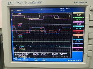
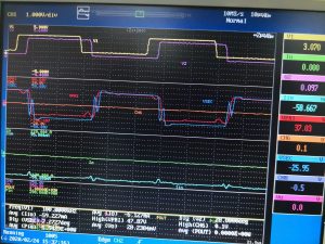
Notice that the upper waveform represents the phase shift between the two bridges lower waveform show amount of voltage flowing. Moreover, the waveforms above show a disturbance this is due to the capacitor issue mentioned before.