Comparison Between Boost, Ćuk and SEPIC
Ćuk Converter:
Two additional converters are going to be evaluated and compared with the rectifier-boost topology. The first one is the Ćuk [11] converter. This converter has two inductors and two capacitors, meaning that it has more passive elements than the boost topology. Additionally, the converter reverses the polarity of the output voltage signal and increase the signal or decrease it depending on the reference value in the closed-loop control circuit or the duty cycle chosen as shown below [7].

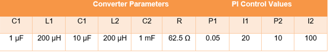
This method varies from both the buck and a boost converter that the energy transfers when the switch is turned on and off is through a capacitor instead of an inductor [7]. Now, for better comparison, we put the input and output voltage for the Ćuk converter to be the same as the boost (Vout = 500 V), and the inductor values to be the same as the boost converter. Additionally, the first capacitor in the Ćuk converter is going to be small since that helps for faster charging and discharging (hint. High frequency) since the time for charging and discharging of a capacitor is directly proportional to the capacitance value [10]. The table below shows the parameter used for the circuit design.
Table 3‑5: Ćuk Parameters.
Below is the block diagram of the Ćuk converter and resulted signals.
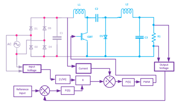
Figure 3‑16: Ćuk Converter.
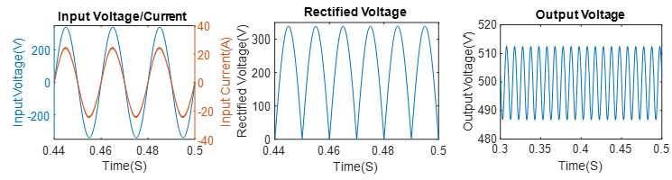
Figure 3‑17: Closed-Loop Ćuk Results.
SEPIC Converter:
The Single-Ended Primary Inductance Converter (SEPIC) converter is another converter that can be used for the PFC topology of the input current. This topology has a similar structure to that of the Ćuk converter except that the second inductor and the diode positions are exchanged. The SEPIC converter has the same number of passive elements as the Ćuk converter [11]. Additionally, the SEPIC converter does not reverse the polarity of the output voltage, as stated in [7].

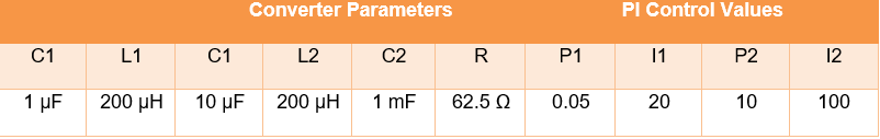
Now, the parameters chosen for this design are the same as the Ćuk converter stated below.
Table 3‑6: Parameters for SEPIC.
Below is the block diagram of the SEPIC converter and resulted signals.
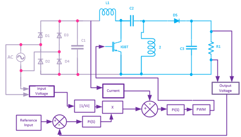
Figure 3‑18: SEPIC Converter.
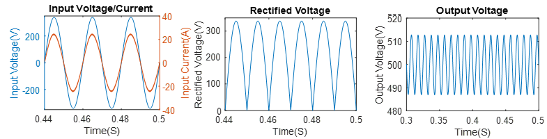
Figure 3‑19: Closed-Loop SEPIC Results.
FFT Analysis of the Boost, Ćuk, and SEPIC
Now, the FFT (Fast Fourier Transform) analysis is supposed to indicate how much ripples are added to a specific signal. For instance, the input current should ideally be a sinusoidal signal with 50 Hz and pf = 1, so that the ripple, in this case, are all the signals with frequencies other than 50 Hz that is added to the desired signal. Additionally, the output voltage can be assumed to be ideally dc, meaning that the desired frequency is 0 frequency, while all other frequencies (ac signals) are undesired ripples that add up to the dc signal.
The measurement used to indicate the percentage of how ideal is the signal is the THD and is assumed that it should be less than 5% for input current, and less than 5% for voltage. The FFT for both the input current and the output voltage for all the three PFC converter’s types are represented in table 3-5 below.
Table 3-7: FFT Analysis of Boost, Ćuk, and SEPIC.
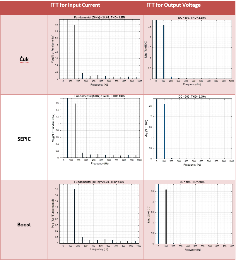
As seen above, the circuit above shows results that are under the acceptable range for both input current and output voltage. For the case of the input current, it can be seen that the boost converter has slightly bigger harmonics than the SEPIC and the Ćuk converter, especially at the third harmonic, which is 1.8% of the desired signal in comparing to approximately 1.6% for Ćuk and SEPIC [17]. This result is expected since the Boost converter has only one inductor, which means less filtering for the input current. The output voltage, on the other hand, shows that they all share the same non-dc harmonics pattern except that the Ćuk converter has more 200 Hz components than the rest. In general, the selection of the SEPIC converter is going to be made since it gives the output voltage directly to the battery while not reversing the output voltage.