- Introduction
- Block Diagram
- Calculation of the Resistance of the Electrodes
- The Size of the Earthing Conductor
Introduction
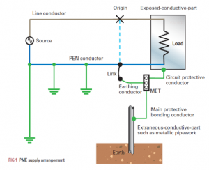
In the beginning, earthing system is an electrical system that is used to provide a path for the current to flow through it when there is a fault in the system. The main motivation for designing an earthing system is human’s safety. So, in case of any fault in the system the current will flow to the earth’s electrode instead of flowing through the human’s body. Based on that, the total resistance of the earthing system must be small as possible so that the current will flow through the path with the low resistance. According to NEC 250.56 standards the total resistance of the system should not exceed 5 Ω. As can be observed in figure 5-1 below, the basic diagram for the earthing system, also, the main components and equipment required for the earthing system such as the earthing conductor, the conductive part such as electrode or rod and the soil which will be used to bury the electrode inside it. As discussed in the previous chapters, there are two main buildings in the sport complex which are the football stadium and sport activities buildings and each one of them will have its own earthing system, but the design procedure will be the same. So, in brief, the main goal of the earthing system is to select the right equipment such the electrodes and their number and the suitable cable for the earthing conductor so that the overall resistance will low as much as possible [22].
Block Diagram
The main requirements of the earthing system are the earthing conductor, the electrodes or the rods and the round conductor. As can be observed in figure 5-2 that illustrates the steps that will be followed to calculate the total resistance and to obtain the main requirements of the earthing system.

Calculation of the Resistance of the Electrodes:
This section will contain two subsections which are the calculation of the resistance of a single electrode and the resistance of the electrodes in the hollow square shape. The first section will explain the procedure of calculating the resistance of a single electrode and the parameters that affects the value of the resistance. In the other subsection, the calculation of the resistance of the electrodes in hollow square shape will be performed, also, the different parameters that influence the resistance’s value will be explained as well.
-
- Calculation of the resistance of the single electrode:
First of all, the electrode is one of the components of the earthing system which is a metallic rod usually made of copper or aluminium. The electrode is installed underground under specific depth and connected to the earth. According to the British standards the resistance of the electrode can be calculated from the following equation:
![]()
From equation 7, the main parameters that will affect the resistance of the electrode are , L and d. where : is the resistivity of the soil in Ω.m. the value of the soil resistivity is varying from one country to another based on the soil type. While L is the length of the electrode in meters and d represent the rod’s diameter in meters.
In this design, the value of the soil resistivity is fixed, while the values of L and d will vary to obtain the minimum resistance. In Qatar, the type of the soil is loam type which is combination of sand and clay with a range of soil resistivity between 30-300 Ω.m as can be observed in appendix B6 [23]. The will be considered to be 165 Ω.m which is the average value for this range, in practice, the soil resistivity of the location is measured by the engineers before the design so that the design will be more precise. But unfortunately, this cannot be applied in this project because of the lack of the needed equipment. The table 5-1 below summarizes the values of the parameters of the earthing system for the loads.
|
Parameter |
Value |
|
Soil resistivity |
165 Ω.m |
|
L length of the electrode |
3.00 m |
| d the diameter of electrode |
0.015 m |
When substituting these values in equation 7, the resistance of the electrode will be obtained:
- Calculate of resistance of the multiple electrodes in hollow square:
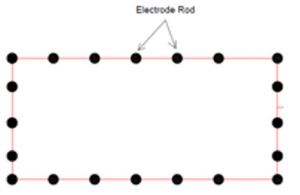
Firstly, as can be noticed from the result of the previous section the total resistance of the system is still much higher than 5 , so, it is required to increase the number of electrodes so that the resistance of the system will decrease. The basic idea of this design is to connect several electrodes in hollow square shape with equal distance between the electrodes and these electrodes will connected in parallel using strip or round conductor so the total resistance will be decreased as figure 5-3 shows. So, there are three steps to be performed:
- Obtain he resistance of the electrodes.
- Calculate the resistance of the round conductor.
- Find the resistance of the total system and compare it with the requirements of the system.
- The resistance of the electrodes:
According to the British standards the resistance of the electrodes in the hollow square shape can be calculated from the following equation:
![]()
From equation 8, the main parameters that will affect the resistance of the electrode are Rr,α , λ and N. where: N is total number of electrodes, is coefficient that will depend on the number of electrodes in each side of the square (n) where![]()
While Rr is the resistance of single electrode and is another coefficient can be obtained by:
![]()
Where R is the resistivity of the single rod, S is the distance between the electrodes in meters and ρ is the soil resistivity. Now, the two variables that will vary are the number of electrodes and the distance between them. While the other two coefficients will depend on these variables. So, by assuming the distance between the electrodes is 3 meters and substituting in equation 10.
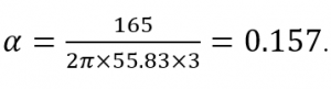 .
.
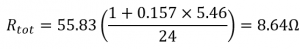
Then, assuming the total number of electrodes is 12 electrodes. By using the equation 9, n will be 4 electrodes. Now, by using the obtained value of n and table in appendix B7, the value of can be obtained easily which is 5.46 [23]. the following table will summarise the parameters of the system:
| Parameter | Values |
| Rr the resistance of single rod | 55.83Ω |
| α | 0.157 |
| λ | 5.46 |
| N total number of rods | 12 electrodes |
| n number of rods side of the square | 4 electrodes |
| S distance between rods | 3.00m |
Finally, to get the total resistance equation 8 will be used:
- The calculation of resistance of the round conductor:
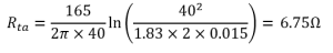
In this section, the value of the resistance of the round conductor will be obtained. The main role of the ground conductor is to connect all the electrodes together in parallel manner. According to British standards the following equation will be used to calculate the resistance of the conductor:
![]()
Where: L is the length of the conductor, d is the diameter of the conductor and h is the depth of the burial all in meters. While k is constant value equal to 1.83 for round conductor [23]. The length of the conductor must be at least 36m so that it can connect all the 12 electrodes together. So, in this design the value of L will be 40 meters. While the depth of burial is a variable that can be changed by the engineer to meet the constraints of the system. In this system the depth of burial will be 2 meters. The table 5-3 below summarises the specification of the design:
| Parameter | Value |
| K | 1.83 |
| L length of conductor | 40m |
| h depth of burial | 2 m |
| D diameter of conductor | 0.015m |
Now, by substituting these values in equation 11, the resistance of the round conductor will be obtained.
- The total resistance of the earthing system:
Finally, the equivalent resistance of the earthing system can be determined by using the parallel connection equivalent resistance.
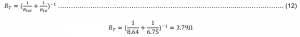
As can be observed, the total resistance of the earthing is almost 3.79 that is lower than 5 which meets the NEC standards mentioned earlier.
The Size of the Earthing Conductor
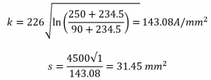
This section will explain the selection of the cable that will be used as an earthing conductor. In fact, earthing conductor is cable that will be used to connect the load with earthing electrodes which mean when there is a fault in the system the current will flow through this conductor to the earth. So, the main aim is to obtain the suitable cross-sectional area of the cable that can handle fault current of the system. The main parameters that will affect the size of the cable are the earth fault current, the fault duration and the temperature. According to the British standards BS 7430:2011+A1:2015 the size of the cable can be calculated using the following equation:
![]()
Where s is the cross-sectional area of the cable in mm2, i is the fault current in A, t is the fault duration in the systemin seconds and k is a constant coefficient that depends on the temperature and the material of the cable in A/mm2. According to KM standards, the earth fault current in 11 kV underground system is 4.5 kA, while the fault duration is 1 second. Finally, k can be calculated by applying the following formula:
![]()
Where K and are a constant coefficient depending on the material of the cable. In this design the material of the cable is copper that has K= 226A/mm2 an =234.50C which can be found in appendix B.8. Moreover, T1 is initial temperature of the conductor, which is the maximum operating temperature of the cable, while T2 is the final temperature of the conductor. Based on Doha cable catalogue the T1 and T2 for XLPE cable which will be used here are 900C and 2500C respectively. Now, all the parameters will be substituted back in equation 14 and 13 to find the required size of the cable.