The simulation will be tested under multiple conditions where the phase shift angle is changed while the input voltage and current, output voltage and current, will be monitored, all the while power delivered will be calculated by getting the average current of the source delivering power as well as its voltage.
- Forward mode (grid to vehicle)
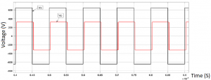
15.47 ͦ (0.27 rad) phase shift:
In this case the charger is working in the forward mode however; this time maximum power will be delivered from source (V1) to source (Battery) (V2).
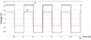
the above figure clearly shows that the primary voltage is leading the secondary voltage which means that power will flow from the primary side to the secondary side (grid to vehicle).
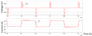
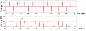
Additionally, the current and voltage on the inductor shown in the above figure indicate that power is being delivered.
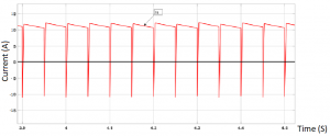
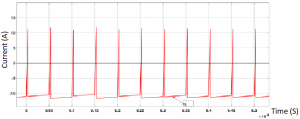
Lastly, the input and output current shown in the previous figures show that maximum power is delivered to the vehicle which is noticeable due to the fact that the input current is positive and the output current is negative. Where power delivered is equal to 3451.5W which is slightly lower than the theoretical value.
- Backward mode
-15.47 ͦ (-0.27 rad) phase shift
This time the charger is working in the backward mode (vehicle to grid), and maximum power is delivered from vehicle to grid.
the previous figure shows that this time the secondary voltage is leading the primary voltage meaning power is flowing from the secondary side to the primary side (vehicle to grid).
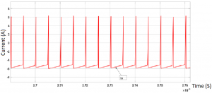
And much like the Forward mode the inductor voltage and current shown in the above figure mean that power is flowing.
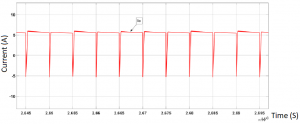
In this case maximum power is delivered from vehicle (V2) to grid (V1) which is evident by the negative current for (Is) in the above figure. Furthermore, the current waveform is similar to the previous case, but both currents are reversed, also the power delivered in this case is –3455.3W which is slightly lower than the theoretical value. Moreover, it is evident that in every phase shift angle there is some losses since the current near the source receiving power is slightly lower than the current at the side delivering power, which means there are slight losses in the system due to the MOSFET’s not being ideal as well as losses on the leakage inductance. Finally it is noticed that in both the forward and backward modes the input and output currents have a dip which repeats, and that is due to the diodes working for a short amount of time allowing current to flow in the opposite direction very briefly.