Closed loop phase shift control
Since the voltage of the battery is not exactly 600V all the time (slightly higher at high state of charge or slightly lower at a low state of charge) the voltage from the grid is changed to match it to operate in zero voltage switching mode, so to make sure that the power delivered is steady and matches the expected result a closed-loop controller is implemented. This controller compares the power delivered in the simulation and the expected power than using a PI controller and other operations this difference is then translated into a change in phase shift which is then implemented and updated in a closed loop. Consequently, the controller makes decisions regarding the phase shift to keep the power at the desired level. Finally, the controller is also responsible for decreasing the amount of power delivered when the state of charge of the battery reaches 80%, all while stopping the charging when the battery is fully charger and stop discharging when a predefined value for the state of charge is reached (eg.20% or 100%).
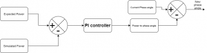
the above figure illustrates the closed loop control in a block diagram that shows how the control works in terms of the phase shift angle.
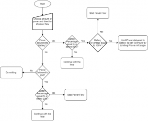
also the figure above shows the other function of the closed loop control in the form of a flowchart, where this part of the control monitors the state of charge of the battery and the chosen power value and direction which then makes decisions based on the parameters of the charger.