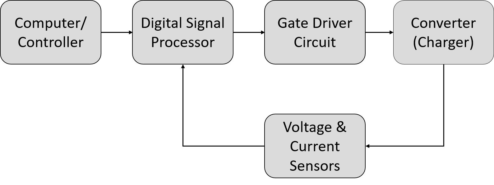
In the practical implementation, controllers are used for controlling the closed-loop operation of DC-DC converters. The microcontrollers, or digital signal processors (DSP), act as the brain of the system and are usually programmed through computer software to execute a specific task. However, power converters cannot be directly connected to the DSP; they are intrinsically connected via a Gate Driver Circuit. Gate driver circuits are used for buffering between the power circuit (converter) and the control circuit (DSP) because DSP cannot supply the power required to the converter. Gate driver circuits ideally have infinite input impedances as not to absorb any power from the DSP, and at the same time, they supply the converter with the required amount of power.
Results
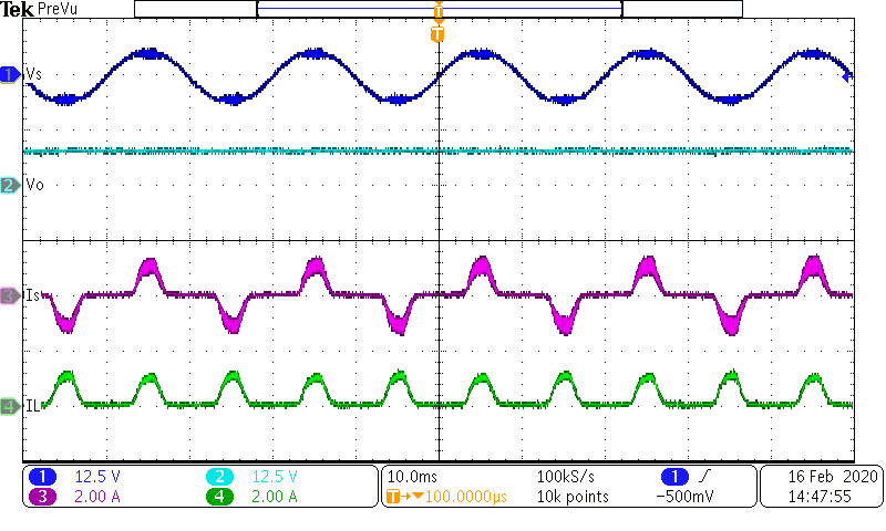
From the simulation results, it was deduced that the phase-modular designs are the optimal designs. Hence, the implementation started with creating the single-phase module. Figures below show the testing for scaled-down implementation of open-loop and closed-loop operations.
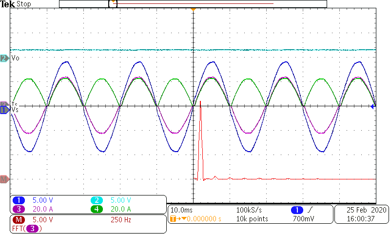
Comparing between the open-loop and the closed-loops operation of the 5W Boost PFC rectifier, the input current waveform has been significantly improved in the closed-loops operation, indicating a lower THD value. The value of the THD can be calculated through the FFT (red waveform), where the third and fifth harmonics are almost eliminated.
Waveform Key:
- Blue: Input Voltage
- Cyan: Output Voltage
- Purple: Input Current
- Green: Inductor Current
-
Implementation of 5W Boost PFC rectifier in Open-loop Configuration
- Implementation of 5W Boost PFC rectifier in Closed-loop Configuration
Go Back to Previous Page
Go Back to FG4 Main Page