This project proposes a design for QU-EVCS infrastructure that responds to the potential increase of EVs in Qatar in the near future. The proposed design takes into consideration the existing campus parking and power distribution system infrastructures. Information and data about these infrastructures were collected from the QU-FGSD, which provided the general masterplan and distribution system drawings of the campus in 2016. However, some of the data and information were provided late and some others were missing and not available with the QU-FGSD, which have created a big challenge for moving forward with the design. To overcome this problem, it was decided to compensate for the missing feeder loads data in some of the old builds substations by estimating it using the meter readings of energy consumption for concerned substations, which were provided by the QU-FGSD for the year 2016.
After studying the existing QU campus parking infrastructure, the most appropriate parking areas were identified and selected for the design. These are the multi-floor car parking, male student housing, female student housing, pharmacy college, medical college, and office building, which were selected due to the information availability and area suitability for installing PV Panels.
The proposed design was modeled and simulated using the ETAP software, which is specialized in power systems analyses. The specification data for the EVCS, PV Panels, and PV inverters that were selected for the proposed design were obtained from their manufacturers’ datasheets. Besides, it was planned to pay a visit to the first KAHARAMAA solar-powered EVCS to get some practical information and data about the installed and working station, but because of the home-confinement and office closure due to COVID-19 pandemic, the visit to KAHRAMAA EVCS was not possible.
The power distribution system base case K1 system was modeled and simulated. The corresponding results are used for identifying the spare capacity available on each bus and also for benchmarking with different design scenarios. The benchmarking is conducted based on system power losses and voltage and power rating limits’ violations. Based on the simulation results, it was noticed that all bus voltage values were within the range of 0.965 and 0.968, which did not exceed ±6% nominal voltage as required by the KAHRAMAA power distribution standard.
The K2 system design consists of installing only EVCS in selected buses which exhibit significant spare power capacity. The simulation results showed significant voltage drop and power losses as expected because of increased system load. However, there was not any violation of the constraints as the numbers of EVCSs connected to each selected bus were chosen based on their spare power capacity.
The K3 system design consists of adding PV panels in substation with large voltage drop and power losses. The simulation results of this scenario showed significant improvement in the system performance. The voltage drop decreased significantly compared with K2 design. Consequently, the power losses were reduced as well.
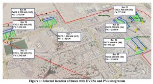
Table 1 summarizes the proposed final QU-EVCS infrastructure design. The selected buses for EVCS and PV installations are buses 6, 7, 11, 16, 18, 20, 29, and 30, which are multi carpark, student housing 3, student housing 1, college of engineering, student housing 2, ofices building, college of pharmacy and student housing 5 respectively.
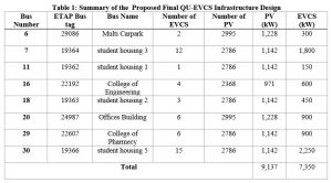
Figure 1 shows the physical location on campus of the above selected buses as per the final design of QU-EVCS infrastructure with the integration of solar energy. It can be concluded that the number of EVCSs can be further increased because by adding PV panels the spare capacities in those buses increase more.