After obtaining the total connected load in chapter 3, the size of transformers and cables will be determined in this section along with voltage drop calculation.
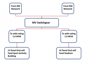
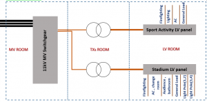
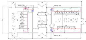
The Substation will be designed to feed the sport complex and its facilities as car parking, sport activity and football stadium. The substation consists of three main rooms which are MV room, transformer’s room and LV room. MV room is the first part of the substation where it will receive the power from KM distribution network at 11 kV level, then, by MV switchgear will feed the two transformers at 11kV level. After that, the transformer will step-down the voltage up-to 415 VL-L. Following, the power will be transferred to LV room by using LV power cables. LV room contains two main LV panels that will distribute the power to sport activity building and the stadium respectively by using smaller LV power cable that will be installed underground as figure 4-1 shows.