To be able to supply the building with electricity for the load calculated in section 3.4, a proper substation should be designed. The substation components will include a medium voltage (MV) trench that link the 11kV transmission lines to the substation, a power correction equipment, a step-down transformer to supply the low voltage panel (LVP) that is connected to all the submain distribution boards, and a diesel generator to supply the emergency load to maintain the operation of these devices in case of failure. The components are explained below:
Power Factor Correction Equipment (Capacitor Bank):
As per Kahramaa manual, the power factor should be a minimum of 0.9 lagging [5]. Thus, a capacitor bank, which is a power factor correction equipment, is required to increase the power factor from 0.8, which is the power factor of the residential building, to 0.9 lagging. The rating value of the capacitor bank can be determined by first finding the needed reactive power, which can be computed by multiplying the maximum demand (section 3.4.1) with the difference between the tangent of the power factor angles as shown below in equation (4-3) [27]:

Then the reactive power value is compared with the available types in Qatar which is 200 kVAR.
Note: according to Kahramaa, the capacitor bank has an automatic controller that is programmed to maintain the power factor at 0.9 minimum lagging and disconnect in case of unity power factor.
Step-down Dry Type Transformer:
Sizing and selecting a suitable transformer are extremely important, as it is the component that step-down the voltage from 11kV (medium voltage) to 415V (low voltage) to provide electricity to the building. The rating of the transformer is chosen based on the type of transformer and the maximum demand of the building. Dry type transformer will be selected since the transformer is installed within the building. Moreover, dry type transformer can handle more power. To determine the rating of the transformer equation 4-4 should be applied. Where the maximum demand is equal to 714466.6 W, as presented in section 3.4.1 and the power factor (PF) is the power factor that is equal to 0.9 because it is corrected by the capacitor bank:
![]()
The rating of the transformer should be 1000 kVA. However, as per Kahramaa manual [5], the current should be calculated using the rating of the transformer as demonstrated in equation 4-5:
![]()
Then, the current computed in equation (4-5) should be less than 95% of the current carrying capacity of the 1000kVA dry type transformer (which has a current carrying capacity equal 1334 A). Therefore, the maximum allowable current for a 1000kVA transformer is 1267 A and the current found is 1104.4 A, so the condition is satisfied. As a result, the step-down dry type transformer that will be used will have a rating of 1000kVA.
Diesel Generator:
In this design, a generator is required as standby system to maintain the operation of the emergency system in blackouts or emergency situations. Thus, the generator should be sized to meet the requirement of the total emergency load that was calculated in section 3.4.2 and the type of the generator should be chosen according to the need of the design, which is a diesel type since it is not costly, and it can power up the load in less than 10 seconds. To select a suitable rating for the diesel generator the wattage value of the emergency load should be converted to kVA by dividing the wattage value by the power factor equal to 0.8 because the generator is not connected to the capacitor bank as shown in equation (4-6):
![]()
According to Kahramaa manual [5], a safety margin should be kept allowing any future increase in the power, the kVA value should be divided by 80%, which will lead to a 248.5 kVA. However, there is no such a size as this, so based on the availability of the diesel generator rating in Qatar the size that will be selected is 250 kVA.
Low Voltage Panel (LVP):
Low voltage panel is located in the LV room and it is also known as the main distribution board. The panel transmit the voltage from the transformer to a divided electrical feed (branches or circuits) because it is easier to control the amount of power supplied to it. These branches represent the rising main and the submain distribution boards or SMDB that will distribute the power for the entire building. In this project, there are eleven SMDB and one rising main connected to the LVP [28].
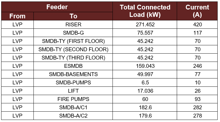
The rising main and the submain distribution boards (SMDB) will be divided as shown in table 4-1 with the total connected load for each one and the current ratings. Details about the SMDB and the riser are presented below:
- Rising main:
Based on the Kahramaa standards, the maximum number of floors that should be supplied by one rising main is six floors. For this reason, the rising will start supplying power from the fourth floor to the ninth floor with a capacity able to supply the total connected load for the six floors. Also, the rising main will distribute the power using the single rising main method. - SMDB for the Ground Floor:
This submain board will include all the load for the ground floor such as the load for the gym, the restaurant, the substation room, etc. - Typical Floors SMSB:
There are three typical SMDBs one for each residential floor (the first, second, and third floors) that are not supplied with the rising main. Every single one of these SMDBs hold the same amount of power because each floor has the same total connected load. - Emergency Submain Distribution Board (ESMSB):
Some essential devices shall be supplied by the emergency submain distribution board that is located on the ground floor. It is connected to both the LVP (in normal case) and the diesel generator (in case of failure) through ATS, which is basically an automatic transfer switch, that converts the connection from LVP to the generator in less than 10 seconds to maintain the operation of these devices. - Basements SMSB:
The three basements are supplied from one SMDB that can power up the laundry room, security room, submersible pumps, basements lightings, and the other general load. - Pumps SMSB:
It is located on the first basement and it is responsible for supplying the storm pumps and the domestic pumps. - Lift:
The passenger lift has its own SMDB, that is positioned on the roof, since it consumes high power. - Fire Pumps:
To avoid oversizing the generator the fire pump is not supplied from the ESMDB, it has a different SMDB that is connected to directly to LVP. It is placed on the roof. - A/C SMSB:
For reliability purposes, the central A/C has two SMDB each supply five units of the A/C that are set on the roof. Also, one of the SMDBs is supplying the domestic pump that work as a booster on the roof.
Table 4-1: SMDB and the Riser Total Connected Load and the Current Ratings
![]()
![]()