Introduction
In this section will primarily concentrated on design an earthing system of outdoor substation. The purpose of the earthing is to provide a safety environment for all equipment’s and all substation personnel. Furthermore, provide a safe pass for fault electric current without exceeding equipment limits. To design such an earthing system will be following IEEE 80-2013 standard [24].
Definitions of AC Substation Grounding
-
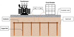
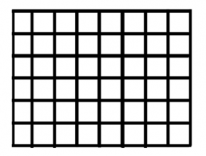
- Ground grid: as figure 5-4 shown, it is a system consist of multiple ground conductors, that are buried deep in the earth, with arranged pattern over substation area [24].
- Ground Potential Rise (GPR): is equal to maximum grid current multiplied by grid resistance. This voltage is the maximum voltage that the station grid can handle in distance grounding point in relation to potential to remote earth [24].
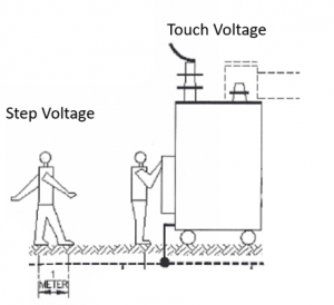
- Touch voltage: when a person is standing and has hand in contact with ground structure, a potential difference between GPR and the surface potential of that point could be occurred [24].
- Step voltage: is an electric potential difference that could a person examined, when bridging 1 m with his feet, without contacting any grounding object inside a substation [24].
Design Procedure
- Step 1: Determine all ground grid parameter’s
All the ground grid parameters are summarized in the following tables:
|
Parameters |
Values |
| Fault current (I0) |
4,500 A |
|
Fault duration (ts) |
0.5 s |
|
Soil resistivity () |
50 Ω.m |
| Crushed-rock resistivity (s) |
5000 Ω.m |
| Material constant of copper (Ks) |
7.06 |
|
Length and width of the grid |
12 m |
|
Area of the grid (A) |
144 m2 |
| Current Division factor (Sf) |
0.6 |
|
Spacing between the conductor (D) |
3 m |
| Surface layer thickness (hs) |
0.102 m |
|
Depth of the grid (h) |
0.7 m |
| Number of rods (n) |
16 |
|
Length of rod |
3 m |
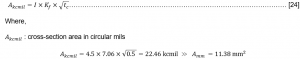
- Step 2: Conductor Size
In this step is to calculate the size of the conductor that will connect all the rods together and form a square grid buried under the substation with depth = 0.7 m. The equation is been used to determine the size of the conductor
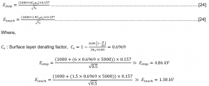
- Step 3: Touch and step voltage criteria
Touch and step voltage criteria will determine the voltages that the substation needs to guarantee the safety of the equipment and all personnel of the substation. All the voltages will be decided by the following equations:
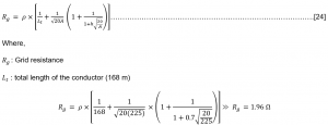
- Step 4: Grid resistance
The total resistance of the grid is depending on the area and total length of conductor as the equation shows.
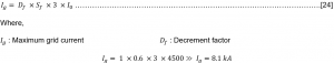
- Step 5: Maximum Grid Current
In this step, calculate the maximum current that could flow in the grid when any fault in any place in the substation occurred. The following equation will determine the current.
- Step 6: GPR
The Ground Rise Potential is required to evaluate, in case the GPR is above the touch voltage , then an additional evaluation is needed
![]()
since, the GPR =12.36 kV is exceeding the Etouch =1.38 kV. Thus, more design analysis is essential.
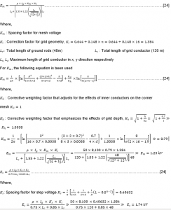
- Step 7: Mesh voltage
In this step, a mesh voltage at the center of the corner are needed to evaluate along with : step voltage between point above the outer corner of the grid.
- Step 8: Compare the values
By comparing Em > Etouch = 1.23 kV > 1.38 kV and Es > Estep= 1.74 kV > 4.86 kV. Thus, the design parameters are been satisfied according the IEEE 80-2013 standard. Therefore, this grounding system can be applied to the substation.