Controlled Current Simulation Results
Now, the same SEPIC system is going to be simulated using Simulink where the simulation of the controlled current SEPIC is done.The entire circuit including the rectifier, SEPIC, and control circuit results are going to be included below. The simulation conducted will be of the controlled current first in which output (current/voltage), input (current/voltage), and (reference/output) current are going to be plotted. The component values and pi coefficients and the SEPIC controlled current results are as follows.
Table 3‑8 SEPIC converter parameters when at the constant current method.
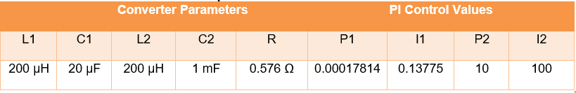
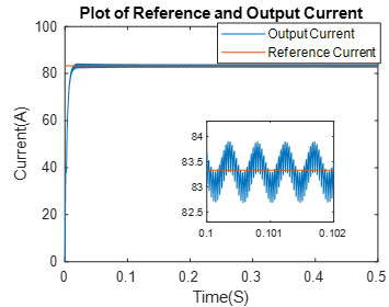
Figure 3‑27: SEPIC Converter for Controlled Current.
The entire rectified SEPIC simulation and results are displayed below:
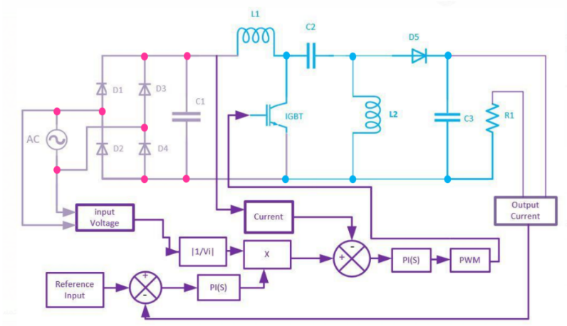
Figure 3‑28: SEPIC Converter for Controlled Current.
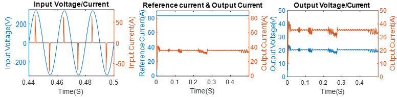
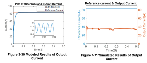
Figure 3‑29: Simulated Results of Controlled Current SEPIC.
Now, the THD was measured to be 299.9%, and the comparison between the model and the simulation is shown below: