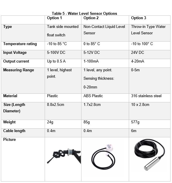
In order to get indications of the available water level, three different sensors that work in different principles were considered as presented in Table 5. Option 1 works by mounting it to the inside of the tank and then be able to make contact with water. When the hanging part is pushed up by the water, it will complete a circuit line, resulting inflow of current, which can be detected by the PLC to take any action, while this option is relatively cheap, it can only detect full tanks, and therefore needs to be in contact with water. Option 2 is a contactless sensor that is mounted on the outside of the tank and detects a change in capacitance, so when there is no water, capacitance lowers and sends pulse to PLC and vice versa. This option is contactless; however, the tank should be clear, not made of metal and its walls should not be thick. Option 3 is a throw-in type, which means the main part is placed at the bottom of the tank usually, then it detects a change in pressure, as when there is more water in the tank, there is more pressure and then the sensors sends an analog sensor according to how much pressure is there, this option while gives more information about how much exactly water there is, it has to be in contact with the water and is quite expensive and heavy. Option 2 was decided to be used for this project, mainly due to it being contactless and that two levels are required to be monitored, the near-empty and full are ones that need to be detected.
