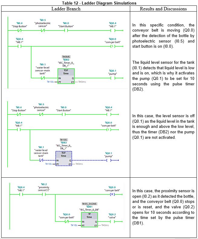
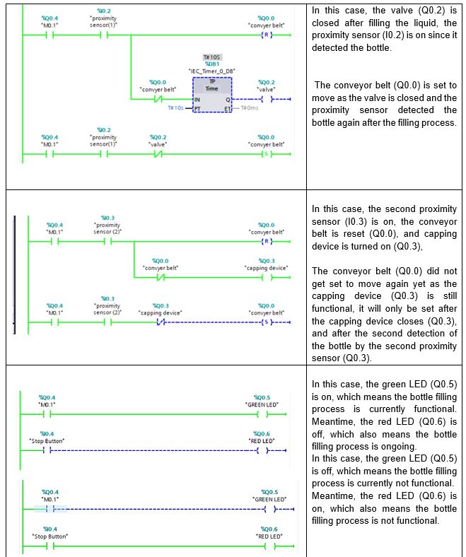
To begin, in order to proceed with the simulation of the ladder diagram created above, Simatic S7-PLCSIM V15.1 software was used to successfully make the simulation compatible with the actual selected Siemens S7-1200 PLC.
Table 12 demonstrates different cases and scenarios for how the ladder diagram will function, depending on the inputs of all sensors and inputs happening throughout that certain timeframe, which would change according to the flow time.

